Safe
Safety functions and system boundaries determine the design. Verification, validation and application-specific evidence accompany the development process.
Safe Modular Secure by Design
ETENAR Safe Config and ETENAR Safe Kit connect system design and engineering for On-Board and wayside applications. Safe computing, configurable inputs and outputs, and communication are matched to your railway application.
For new and existing railway systems: assess obsolescence early, plan replacements and modernise functions in stages.

Background imageAI-generated concept visualisation
Safety functions and system boundaries determine the design. Verification, validation and application-specific evidence accompany the development process.
Compute assemblies, I/O and segments form a central or distributed architecture. Installation and communication follow the On-Board or wayside task.
Secure Boot, secure updates and access control are considered in the architecture. Selection and operating conditions follow protection needs and the product variant.
A shared technical foundation connects different railway tasks. Functions, interfaces and operating conditions determine the design for each system.
Wayside signalling infrastructure includes signals, axle counters, turnouts and point machines, computer-based interlockings, level crossings and object controllers. Distributed assemblies connect sensors and actuators with their control and safety functions. Replacement and modernisation take existing interfaces and operating conditions into account in the system design.
Door systems and controls, TCMS, propulsion and vehicle communication connect local tasks with the vehicle architecture. Braking, SiFa and speed functions are further application areas. Safe computing, I/O and communication interfaces are matched to the On-Board application and the existing system baseline.
ETCS, RBTC, CBTC, ATO and ATP are among the engineering application areas, alongside safe displays, ATS and ATC. EULYNX, RaSTA and FSE form part of the interface and communication context. The specific railway application determines which functions, interfaces and evidence are required.
ETENAR Safe Config and ETENAR Safe Kit together form the platform for industry and rail. Architecture, system software and engineering work together for your railway application.
Functions, assemblies, signals and installation locations are designed alongside the system software. This defines architecture, signal mapping and integration requirements, from compact configurations to distributed systems.
Tools and libraries support configuration, application development and extension. The appropriate toolchain connects engineering tasks with diagnostics and commissioning preparation. The agreed version defines the available functions.
The development foundation comprises SiTCommand with generic hardware and system software, and SiTKit with engineering tools and libraries.
Explore the technology platformCompute assemblies, binary and analogue I/O, and mixed assemblies form the required structure. Form factor and distribution follow the application.
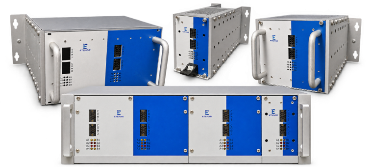

An individual module for processing, I/O or fieldbus functions.
Selected modules combined in one unit.
Assemblies for one functional part of the application.
Connected segments for the complete application.
Three areas that shape the system design.
SiTCSafeCom supports safety-related Ethernet communication between assemblies and segments.
Compute and I/O resources can be distributed according to the selected configuration. Independent or communicating applications can run on one or more controllers.
3U and DIN-rail formats, independent or redundant supplies, and UPS integration support different installation concepts.
The configuration is selected according to operating conditions. Galvanically isolated, hot-pluggable I/O assemblies can form part of the selected configuration.
The technical foundation supports a geographic configuration check: intended assembly placement is verified at startup.
An incorrect placement detected during this check stops the system. Behaviour follows the defined system configuration.
ETENAR Safe Config defines the system design. ETENAR Safe Kit supports engineering from functions and installation through to application and commissioning. Defined roles make handovers between functional specification, physical installation and application traceable.
Define functions, system boundaries and logical architecture. Sensors, actuators and required control tasks establish a common starting point.
Map sensors and actuators to physical I/O. Modules, segments, locations and power supplies are brought together in the installation.
Implement specified behaviour on controllers and, where applicable, I/O assemblies. Configuration and application logic are aligned.
Integrate application and hardware in the target system. Diagnostics, testing and documentation support commissioning and final validation.
A shared system baseline provides the foundation for managing obsolescence. When assemblies are discontinued, affected functions, interfaces and existing evidence are assessed together. Replacement, migration and additional testing can then be planned as one coordinated change.
Obsolescence · Installed systems and modernisation
Vehicles and infrastructure often remain in service longer than individual electronic assemblies are available. Discontinuation and limited spare-part availability make obsolescence a system-level concern. Modular architecture supports targeted replacement and staged modernisation.
The starting point is the existing hardware and software baseline, interfaces, operating conditions and evidence. Together, we assess replacement options, effects on existing functions and the migration step required. Evidence that remains applicable and any additional testing are determined for the new configuration.
Discuss obsolescence and modernisationIdentify hardware, software, configuration and evidence; record discontinued assemblies and spare-part needs.
Review replacement options, interfaces and effects on functions and unchanged parts of the system.
Define migration steps, additional tests, documentation and responsibilities for the specific railway application.
Identifying discontinuations early creates time to coordinate replacement options and testing. Evidence that remains applicable can limit additional effort. Scope and timing depend on the specific railway application.
Assemblies, functions and evidence that remain suitable provide the starting point for modernisation. Targeted replacement can help retain proven parts of the system and focus engineering and testing on the affected changes.
Replacement assemblies and migrations remain linked to a clear system baseline. Effects on safety, security and interfaces are assessed together, helping coordinate modernisation, integration and recommissioning.
Obsolescence becomes part of planned railway system development rather than a short-term replacement problem.
Assessment and authorisation requirements are determined for the specific vehicle or infrastructure application. Evidence for an assembly does not replace assessment of its integration.
Functional safety and cybersecurity accompany architecture and engineering. Measures, tests and responsibilities are defined for the specific configuration.
The technical foundation supports Basic Integrity functions and SIL applications up to SIL 4. Safety integrity and evidence relate to the specific function and system configuration. Safety support, verification, validation, qualification and test automation support development.
Secure Boot, secure updates, access control and key management are among the security building blocks available in the technical foundation. Selection and operating conditions depend on the product variant, protection needs and security concept.
Approval of a railway application remains tied to its requirements, integration and application-specific evidence.
The technical context includes IEC 61508, EN 50126, EN 50128, EN 50129 and EN 50716, alongside IEC 62443 and railway cybersecurity under IEC 63452 or CLC/TS 50701. Applicable requirements are established for each project.
New applications and existing systems need coordinated development. Changes to functions and interfaces are connected with integration, testing and documentation. For modernisation, affected interfaces and existing system assumptions remain the starting point for assessing changes.

ETENAR and Safe.inTrain work together on architecture, hardware, software and test planning. Platform technology and railway-specific engineering are combined for the railway application. Delivery scope and responsibilities are agreed for each project.
Our partnershipWith functions, interfaces and operating conditions. For obsolescence, we also examine the existing system baseline, affected assemblies and known discontinuations. Together, we agree the replacement or migration approach, engineering scope and evidence required.
Hardware, software version, configuration and documentation are agreed within the delivery scope. Test results and operating conditions remain associated with the system baseline, supporting integration, maintenance and later extensions. This makes it possible to identify the tested baseline on which a new variant is built.
On-Board or wayside: let’s discuss your new development, discontinued assemblies or modernisation of an existing system.